This page provides detailed information about the hardware of the Sawyer robot.
Sawyer Hardware Overview
This section provides a basic overview of the hardware that makes up the Sawyer robot. For more technical specifications, see our Sawyer Arm Specifications section of this page.
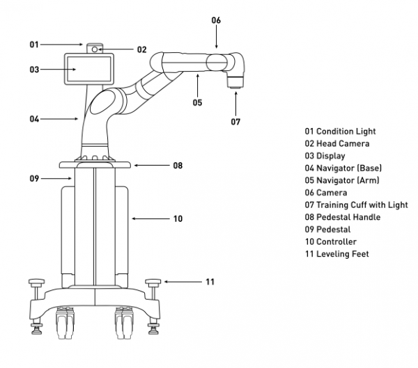
Sawyer Overview
Training Cuff
Use the training cuffs to move the arm, manipulate the state of the gripper, and secondarily, to select on-screen options.
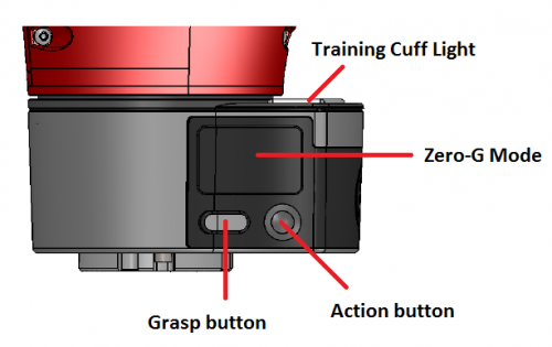
- Zero-G Mode - Squeeze this switch at the indentation in the cuff to move the robot’s arm. When this switch is squeezed, the blue indicator on the arm’s navigator button lights up.
- Grasp Button - Press to toggle a parallel gripper open or closed, or a vacuum gripper on or off.
- Action Button - Press to select items on the display screen. Create waypoints, Hold actions; select, copy, or move actions on the task map, as well as outline a visual search area.
- Traning Cuff Light - Indicator light to provide feedback when actions are performed and display the current state (ie: running in zero-g mode) of the arm.
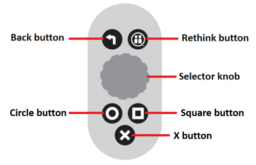
Use the navigator on the arm or base to scroll to and interact with options on the screen.
Sawyer Electrical Specifications
| Description | Spec |
|---|---|
| Interface | Standard 120VAC power. Robot power bus and internal PC both have “universal” power supplies and support 90 - 264V AC (47 - 63Hz) |
| Max Consumption | 4A at 120V AC, 480W max per unit |
| Electrical Efficiency | 87% to 92% |
| Power Supply | Uses industrial-grade DC switching power supply for robot power bus |
| Tolerance to sags | Sags tolerated to 90V. Sustained interruption will require manual power-up |
| Voltage Flicker | Holdup time 20mS |
| Voltage Unbalance | Single phase operation only |
Sawyer Environmental Specifications
| Description | Spec |
|---|---|
| Environment | Indoor Use |
| Altitude | Up to 2000 meters |
| Operating Temperature | 0°C to 40°C |
| Relative Humidity | 80% for temperatures up to 31°C, decreasing linearly to 50% relative humidity at 40°C |
| Pollution Degree | 2 |
Sawyer Arm Specifications
The arm of the Sawyer Robot is the most important component of the robot and having a solid understanding of the different specifications of the arm is crucial when it comes to understanding how the robot operates. The information in the sections below will provide you with the knowledge necessary to gain a better understanding of how the Sawyer works.
Joint and Link Names
Sawyer joint and link names are referenced many times in technical documentation and will be referenced by Rethink Robotics support representatives regularly. The diagram below labels the joints and link of the Sawyer arm.
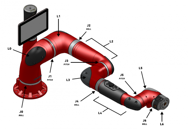
The joint and link naming for the Sawyer arm starts at the base and increases incrementally up to the wrist. The joints are named J0 - J6 and the links are named L0 - L6.
The joints in the Sawyer are also classified into two categories (roll or pitch) by their movement. The small table below lists each joint in one of these two categories.
| Roll | Pitch |
|---|---|
| J0, J2, J4, J6 | J1, J3, J5 |
Link Lengths
Link lengths for Sawyer's joints are measured in mm, from the center of one joint to the center of the next. They can be found in the image and table below.
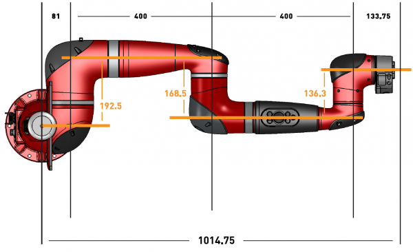
| Link Name | Length |
|---|---|
| L0 | 81mm |
| L1 | 192.5mm |
| L2 | 400mm |
| L3 | 168.5mm |
| L4 | 400mm |
| L5 | 136.3mm |
| L6 | 133.75mm |
Range of Motion - Roll Joints
The range of motion of each roll joint is presented below. The overall joint range is specified.
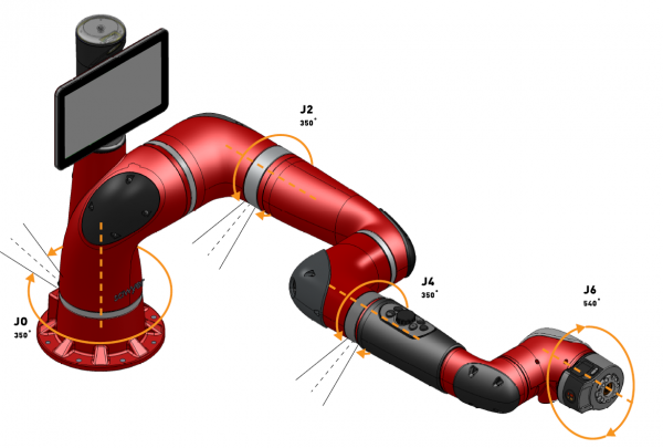
| Joint Name | Range (Degrees) |
|---|---|
| J0 | 350 |
| J2 | 350 |
| J4 | 350 |
| J6 | 540 |
Range of Motion - Pitch Joints
The range of motion of each pitch joint is presented below. The overall joint range is specified.
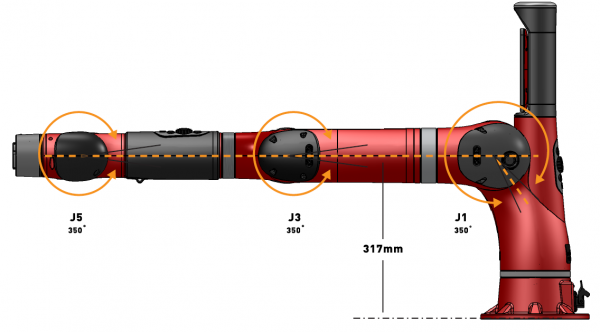
| Joint Name | Range (Degrees) |
|---|---|
| J1 | 350 |
| J3 | 350 |
| J5 | 350 |
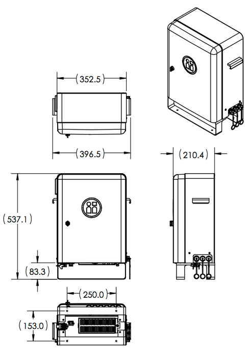
Control Box
General Dimensions
Note: All dimensions are in millimeters.
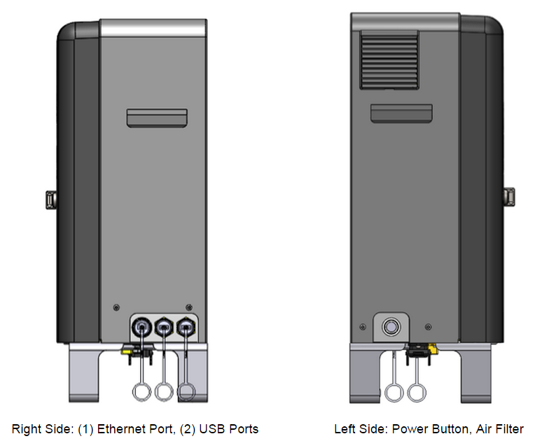
Ports and Devices
Side View
Bottom View
- Inputs:
- Power
- Air
- Outputs
- Air (4x)
- Power and Data
- Video
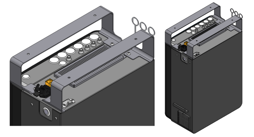
Inside View
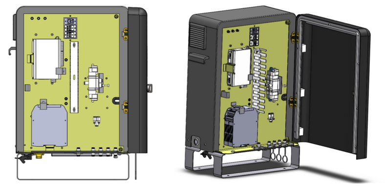
- Terminal Unit (8 Digital Inputs, 8 Digital Outputs)
- Safety Rated Controller
- Solenoid Valve (2x)
- Ethernet Port (For Rethink Use Only - Not accessible)
- USB Port (2x)
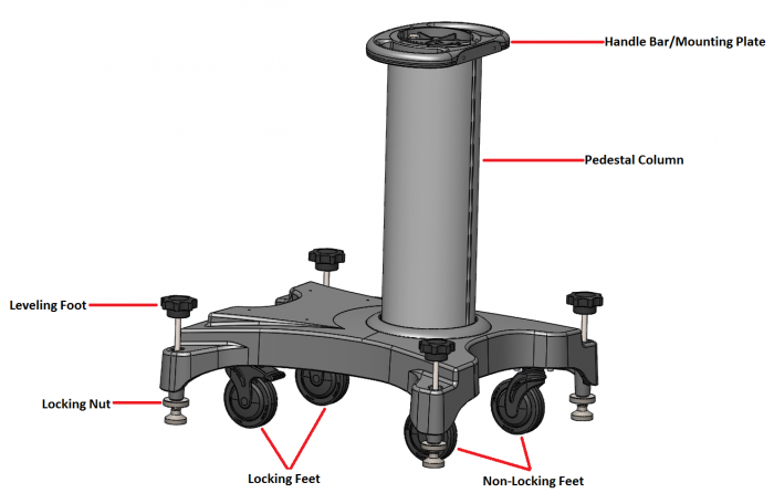
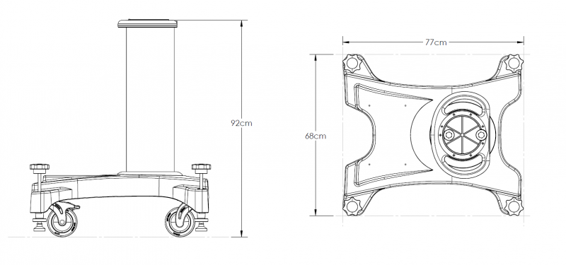
Pedestal
General Dimensions
Note: All dimensions are in centimeters.
Overview