Description
Baxter is a humanoid, anthropomorphic robot sporting two seven degree-of-freedom arms and state-of-the-art sensing technologies, including force, position, and torque sensing and control at every joint, cameras in support of computer vision applications, integrated user input and output elements such as a head-mounted display, buttons, knobs and more.
The Baxter Robot was designed for continuous operation and can run 24/7 for expended periods of time without the risk of damaging the hardware of the robot. It is recommended that the robot be connected to an uninterruptible power when running continuously in order to prevent hard drive corruption in the event of a power outage that can cause an improper shutdown of the robot. If the hard drive of the robot becomes corrupt due to an improper shut down, a fresh install (or factory reset on robots running v1.2 or later) will be required.
Baxter Arm Specifications
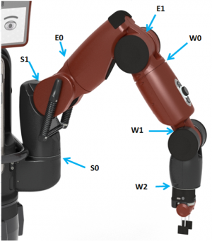
Joint Names
Baxter's joint names are mentioned a number of times in this documentation. A labeled diagram can be found below (S=Shoulder, E=Elbow, W=Wrist)
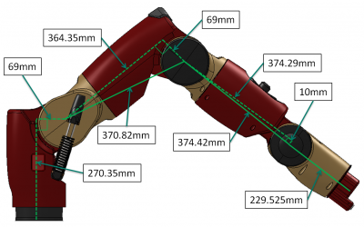
Link Lengths
Link lengths for Baxter's joints are measured in mm, from the center of one joint to the center of the next. They can be found in the image below.
Range of Motion - Bend Joints
The range of motion for each bend joint is presented below. The table shows the measurements in degrees and radians

| Joint | (Degrees) Min limit | Max limit | Range | (Radians) Min limit | Max limit | Range |
|---|---|---|---|---|---|---|
| S1 | -123 | +60 | 183 | -2.147 | +1.047 | 3.194 |
| E1 | -2.864 | +150 | 153 | -0.05 | +2.618 | 2.67 |
| W1 | -90 | +120 | 210 | -1.5707 | +2.094 | 3.6647 |
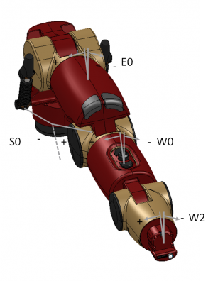
Range of Motion - Twist Joints
The range of motion for each twist joint is presented below. The table shows the measurements in degrees and radians.
| Joint | (Degrees) Min limit | Max limit | Range | (Radians) Min limit | Max limit | Range |
|---|---|---|---|---|---|---|
| S0 | -97.494 | +97.494 | 194.998 | -1.7016 | +1.7016 | 3.4033 |
| E0 | -174.987 | +174.987 | 349.979 | -3.0541 | +3.0541 | 6.1083 |
| W0 | -175.25 | +175.25 | 350.5 | -3.059 | +3.059 | 6.117 |
| W2 | -175.25 | +175.25 | 350.5 | -3.059 | +3.059 | 6.117 |
Maximum Joint Speeds
| Joint | Maximum Speed |
|---|---|
| S0 | 2.0 |
| S1 | 2.0 |
| E0 | 2.0 |
| E1 | 2.0 |
| W0 | 4.0 |
| W1 | 4.0 |
| W2 | 4.0 |
Joint Flexure Stiffness
| Joint | Stiffness |
|---|---|
| Small Flexures (W0, W1, W2) | 3.4deg @ 15Nm (~250Nm/rad) |
| Large Flexures (S0, S1, E0, E1) | 3.4deg @ 50Nm (~843Nm/rad) |
S1 Spring Specifications
| Description | Spec |
|---|---|
| Spring Type | JIS standard die spring: ASF 35 X 200 |
| Free Length | 200 mm |
| Stiffness (K) | 9.6 N/mm |
| Operating length | 101 mm - 154 mm |
Joint Sensor Resolution
- The resolution for the joint sensors is 14 bits (over 360 degrees); so 360/(2^14) = 0.021972656 degrees per tick resolution.
- All of the joints have a sinusoidal non-linearity, giving a typical accuracy on the order of +/-0.10 degrees, worst case +/-0.25 degrees accuracy when approaching joint limits. In addition, there may be an absolute zero-offset of up to +/-0.10 degree when the arm is not calibrated properly. Be sure to tare and calibrate the arms if you're trying to minimize accuracy errors in the joint sensors.
Note: The performance of the joint controllers is a separate matter; ultimately, the accuracy of the controller is only limited by the accuracy of the sensors. In a case where joint position controllers are included, we use a threshold to determine when the joint states are "close enough" to the commanded joint angles to call it acceptable. In the baxter_interface for the RSDK, we use a default threshold of: JOINT_ANGLE_TOLERANCE = 0.00872664626 radians (0.5 degrees), which is set in settings.py and used by the limb interface and the joint_position examples. If you want to improve the accuracy, you can write your own controller to adjust the setpoint and to overcome any steady-state error in the internal low-level controllers. Even when the joint controller is slightly off the target position, it always knows exactly how far off it is, via the joint position sensors.
Peak Torque
The peak torque specification refers to the maximum amount of torque that can be applied to each joint.
| Joint | Peak Torque |
|---|---|
| S0,S1,E0,E1 | 50Nm |
| W0,W1,W2 | 15Nm |
Other Hardware Specifications
Camera Specifications
| Description | Spec |
|---|---|
| Max Resolution | 1280 x 800 pixels |
| Effective Resolution | 640 x 400 pixels |
| Frame Rate | 30 frames per second |
| Focal Length | 1.2mm |
On Board CPU
| Description | Spec |
|---|---|
| Processor | 3rd Gen Intel Core i7-3770 Processor (8MB, 3.4GHz) w/HD4000 Graphics |
| Memory | 4GB, NON-ECC, 1600MHZ DDR3 |
| Hard Drive | 128GB Solid State Drive |
Component Weights
| Description | Spec |
|---|---|
| Total weight (with pedestal) | 298 lbs / 135.2 kg |
| One Arm | 47 lbs / 21.3 kg |
| Torso | 70 lbs / 31.8 kg |
| Pedestal | 134 lbs / 60.8 kg |
Electrical Power
| Description | Spec |
|---|---|
| Battery Operation | DC-to-120V AC Inverter (Note: the Baxter robot has an internal PC, which cannot be powered directly off of 24V DC) |
| Interface | Standard 120VAC power. Robot power bus and internal PC both have “universal” power supplies and support 90 - 264V AC (47 - 63Hz) |
| Max Consumption | 6A at 120V AC, 720W max per unit |
| Electrical Efficiency | 87% to 92% |
| Power Supply | Uses medical-grade DC switching power supply for robot power bus |
| Tolerance to sags | Sags tolerated to 90V. Sustained interruption will require manual power-up |
| Voltage Flicker | Holdup time 20mS |
| Voltage Unbalance | Single phase operation only |
Miscellaneous Specifications
| Description | Spec |
|---|---|
| Screen Resolution | 1024 x 600 pixels |
| Positional Accuracy | +/- 5 mm |
| Max Payload (including end-effector) | 5 lb / 2.2 kg |
| Gripping Force (max) | 35N or 8 lbs |
| Infrared Sensor Range | 1.5 – 15 in / 4 – 40 cm |